Progress Bar

Skip to main content

Jaycar
...

Arduino Clap Light

Arduino Clap Light

Difficulty
Sight & Sound

Summary

The “Clapper” is a sound-activated switch introduced in the USA in the 1980s. It is a box that plugs into a power point and allows two appliances to be connected. According to the motto, “Clap on! Clap off!”, you could simply clap to switch an attached device on or off.

It toggled one appliance on or off when two claps were detected. Another appliance would respond to three claps. By some accounts, it could be too sensitive, reacting to other sounds or even people talking.

Most people used it to control a light or lamp since they are unlikely to cause harm if switched on or off at the wrong time. This simple project provides a similar function.

Materials Required

1
1
1
1
1
1

Such a device is easy to build using an Arduino Leonardo board and a module capable of detecting sound. To save ourselves from getting too close to mains voltages, we’ve added a 433MHz transmitter to provide remote control of a few different types of radio-controlled devices.

This will allow you to control either a wireless power point such as Jaycar’s MS6148, or a commonly installed ceiling fan and light combination (sold under the ‘Brilliant’ brand), which incorporates an RF remote control. In both cases, the circuit transmits the same signal as the remote control, so the existing hand controller can still be used.

Since we are providing the Arduino source code, you could adapt it to control another device, such as a relay module or even something simple like a light-emitting diode (LED) connected directly to the Leonardo board.

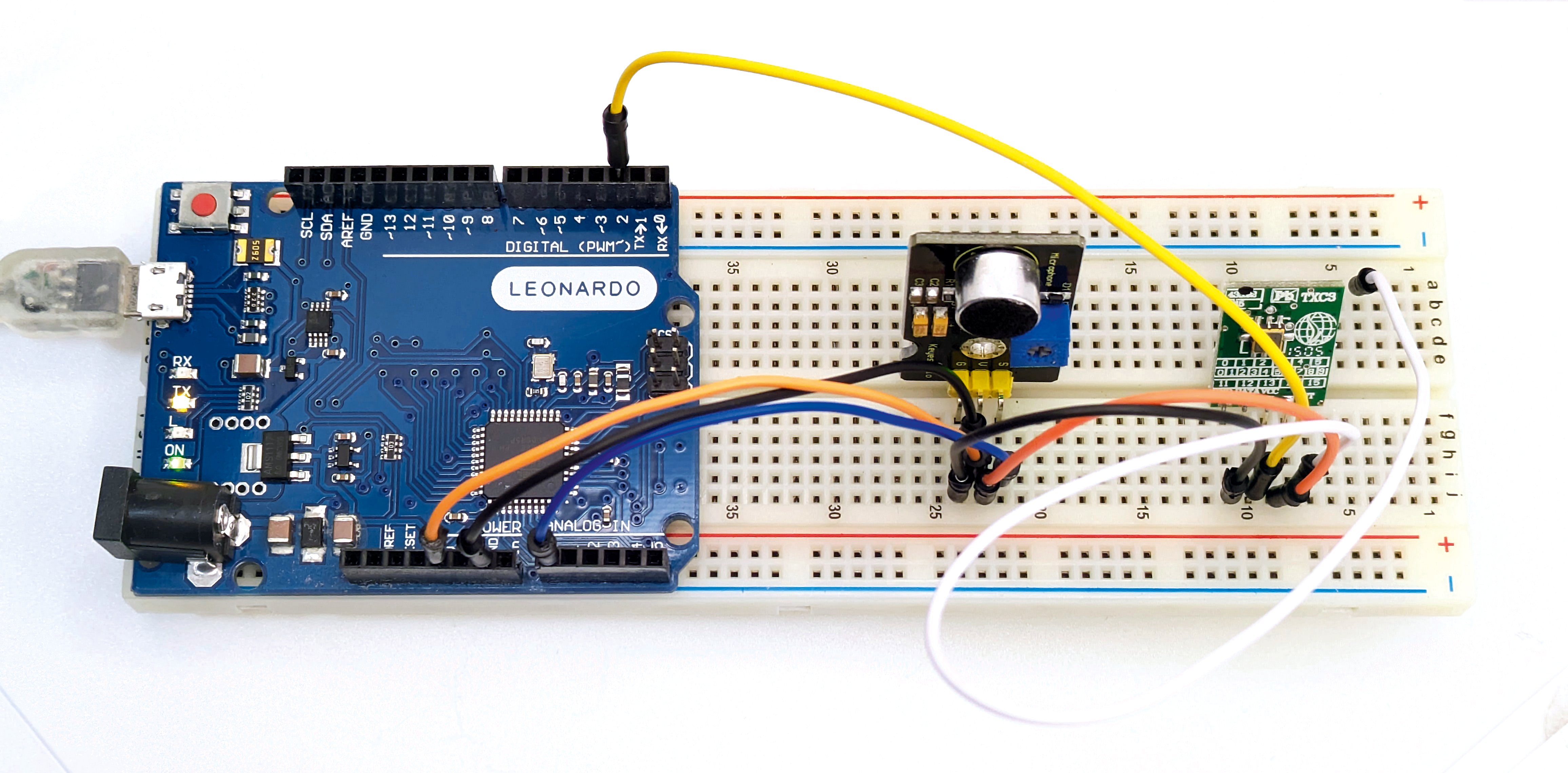
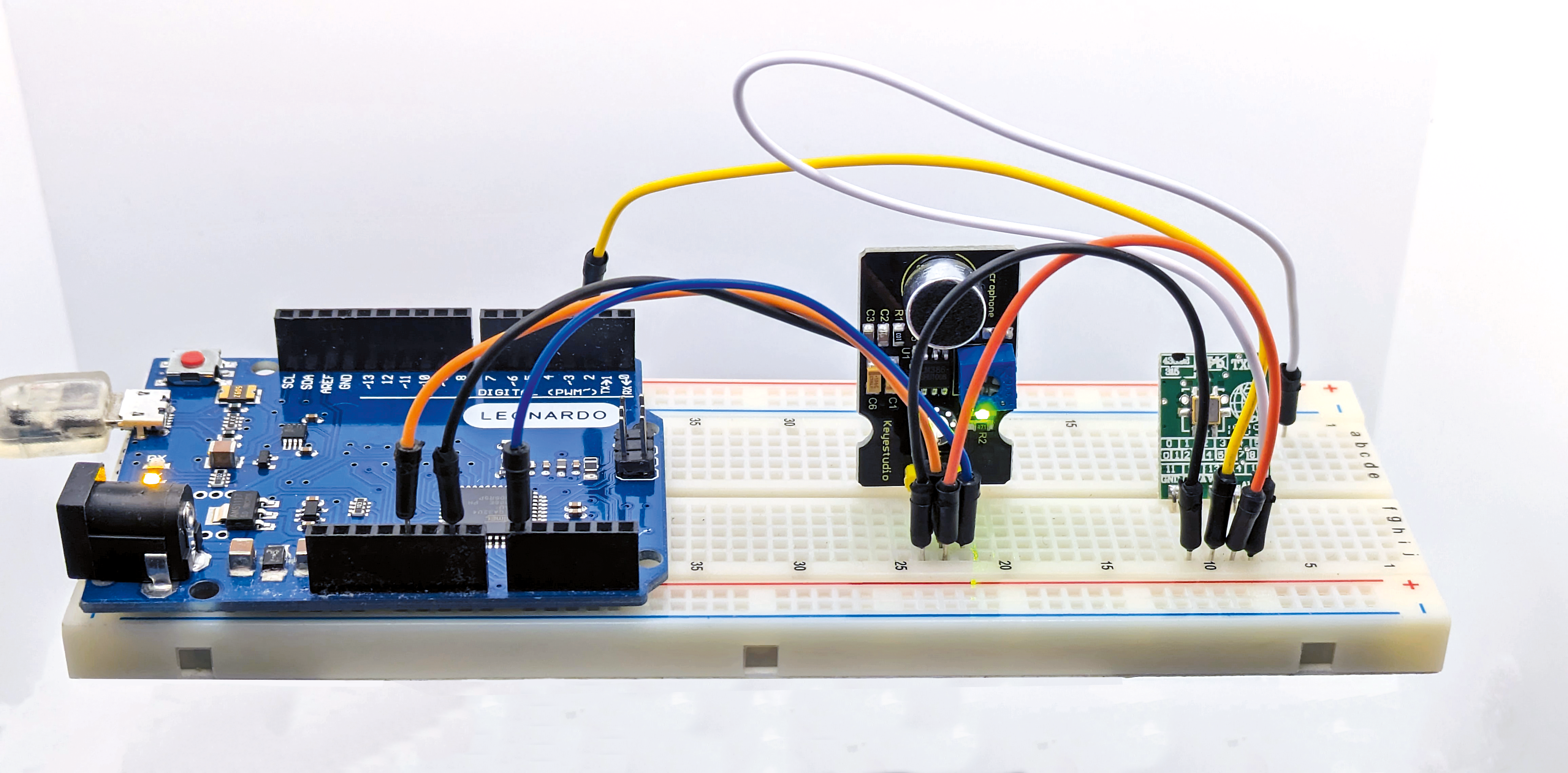
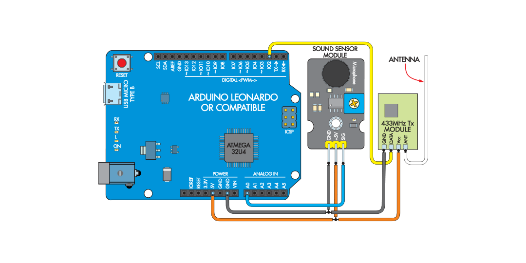
Fig.1 shows the wiring diagram. You can also see how we have laid it out in the photos. We used Blu-Tack to attach the Leonardo to a breadboard, then fitted the modules to the breadboard and connected them with jumper wires.

The Leonardo monitors the analogue signal from the sound sensor module and then sends a digital signal to the wireless transmitter module at the appropriate time.

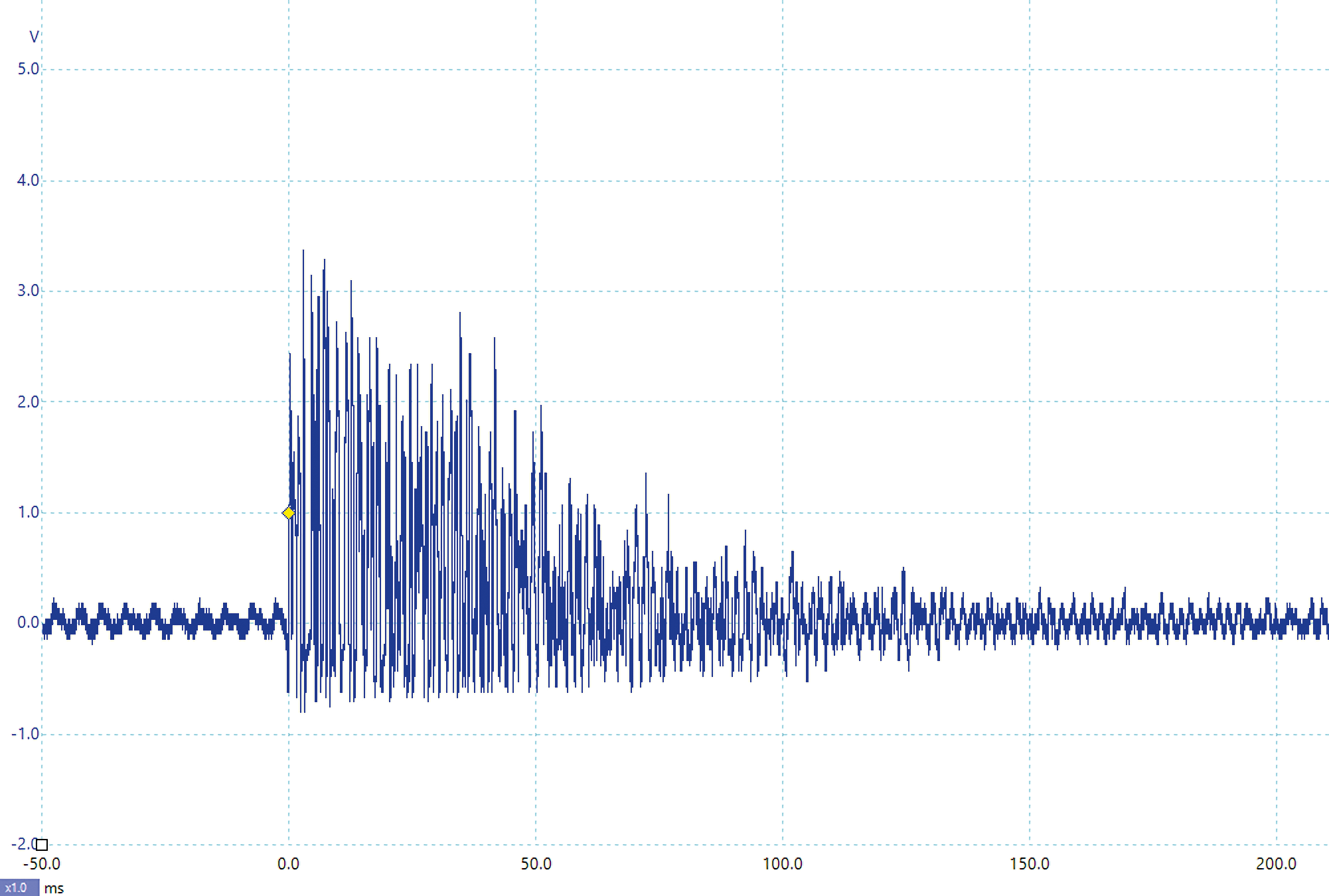
Since the sound sensor module delivers an analogue signal, we must perform some processing to distinguish claps. Scope 1 shows the analogue signal presented by the sound sensor module in response to a clap; it is the positive half of the raw audio waveform. The negative half of the waveform is clipped to around 0V by a diode on the module.

The Arduino sketch

We can’t easily differentiate claps from other short, sharp sounds, such as knocks. Still, you might prefer to make a knocking sound to control it. We are basically trying to detect a sharp increase in volume.

To detect claps, we need to smooth out the waveform to get a signal corresponding to volume (rather than instantaneous amplitude). We use ‘exponential smoothing’ because it is straightforward to implement. Adding an RC (resistor and capacitor) low-pass filter circuit would have the same effect, but we can do exponential smoothing in software without adding any parts.

We then apply some thresholds to distinguish claps from other sounds. We detect the start of a clap when the smoothed value rises above a certain level and its end when the value falls below a different, lower level. This is called hysteresis and is another way to separate claps in a noisy environment.

Once one clap is detected, a timer runs for one second and further claps within that second are counted. Thus, the software can detect multiple claps in close succession. The Leonardo’s onboard LED is also lit while each clap is detected.

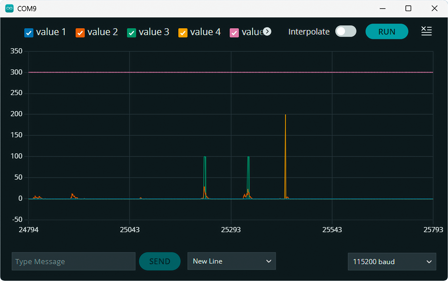
Scope 2 shows the Arduino Serial Plotter debugging data. The orange trace is the smoothed volume signal; each peak corresponds to what is seen in Scope 1. The green trace shows the claps being detected, while the yellow spike shows the one-second counter expiring, having detected two claps (indicated by the peak reaching 200 on the vertical scale).

Note how the smaller orange peaks are ignored. The other two traces ensure that the plotter maintains a useful range.

RF communication

Wireless remote controls use different digital protocols; we have provided software libraries to encode the desired channel and function. We’ll delve into that a bit later during our setup and testing.

The digital RF signals are pretty slow (compared to some digital protocols) and are simply ‘bitbanged’ with timed delays. During the period when the Arduino Leonardo is producing the digital RF transmission signal, it does not monitor or respond to a clap signal, but we don’t think that is a big deal, as you would usually not send a second command until you observed the original one being obeyed.

The sketch also takes input on the Serial Monitor, so typing ‘1’ will have the same effect as making one clap, ‘2’ for two claps and so forth; this is handy for testing. We can handle cases up to five claps, since that was about the most we could achieve in one second. It wouldn’t be hard to update the code to deal with more if you wanted to.

Wind the potentiometer on the sound sensor module fully clockwise; this is the highest gain and thus sensitivity setting. Referring to Fig.1, wire it up to the breadboard and Leonardo, but don’t connect the transmitter module. This will allow us to check the operation of the clap sensor.

Connect the Leonardo to a computer and upload the Clap_Light sketch (available from siliconchip.au/Shop/6/418). If you open the serial plotter, you should see something like Scope 2. If the ‘L’ LED on the Leonardo flashes when you are not clapping, turn the sound sensor module pot anti-clockwise until it settles down.

If there is no response to claps, you can turn it clockwise. Find a level such that the LED flashes when you clap but not other times. There is also one LED on the sound sensor module that shows when it is powered, so if it isn’t on, there might be a problem. Other AVR main boards like the Uno, Nano, and Mega should work, although we haven’t tested them.

With that working, connect the transmitter module as per Fig.1. Note that one end of the ANT wire for the transmitter module plugs into an empty row on the breadboard, so the antenna wire doesn’t float around.

Using the Jaycar MS6148 (or similar) wireless outlet requires a pairing step; you can also refer to the instruction manual. Power on the outlet and activate the ON function while its LED is flashing. The default sketch lets you do that using the ‘3’ command on the serial monitor. Then use ‘3’ and ‘4’ to check that the outlet switches on and off as expected.

Finally, test the clap response while watching the serial plotter to confirm proper operation. The remote control for the MS6148 can control four separate outlets; the rfPowerPoint.h file shows the #defines you can use to emulate these different controls. You can also refer to the doThreeClaps() function in our sketch; the ppSend­RF() function is designed to work with these outlets.

The ‘Brilliant’ fan and light controllers are typically hardwired by an electrician and have a remote control that looks like the one shown in Photo 2. Photo 3 shows the coding DIP switches inside the battery enclosure.

You can see that this one is set to binary 0b1001 or 9, which is the channel number used in the sendCommand() function called by the doTwoClaps() function. If your remote control has a different coding, change the function to use that number instead of 9.

Other functions of the Brilliant remote control are listed in the rfFan.h file. There don’t appear to be distinct off or on functions for the light, but there is a code that will turn both the fan and light off together.

Future Improvements

The Clap Light is quite accurate, but we found it still occasionally reacted to other sounds. For this reason, we have avoided making it respond to single claps. We recommend you do the same and also be careful not to connect anything that might be dangerous if unexpectedly turned on or off.

Similar projects you may be interested in
Atari Punk Synth
Sight & Sound
Atari Punk Synth
Difficulty

Wireless Garden Monitor
Sight & Sound
Digital Photo Frame
Difficulty

Silent Alarm Clock
Sight & Sound
Silent Alarm Clock
Difficulty

Sight & Sound
Ultrasonic Parking Assistant
Difficulty