To help build some of the ‘links’ on the Coding Shield, we use the legs of the components, so be careful not to cut the legs except where noted. It’s possible to solder them on afterwards, but it’s usually easier to not cut them.
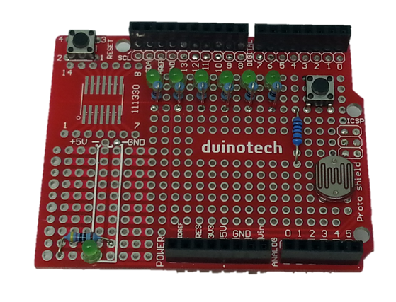
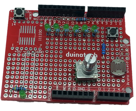
Start by getting out the LED’s, and solder onto the Prototyping Shield as shown, making sure that the cathodes (short leg with flat on body) is furthest from the digital pin side (facing the bottom of the board). The power LED at bottom left has the cathode to the left. The leftmost top LED is in the top left hole.
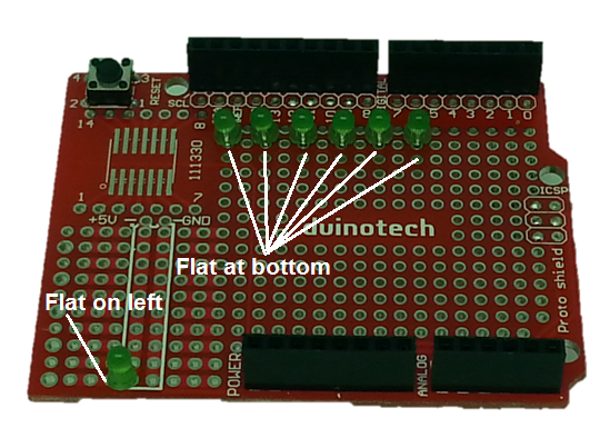
Solder the legs in place, then bend the anodes (closest to the top) over and solder them to D8-D13, then trim.
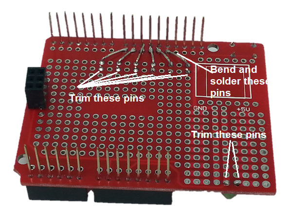
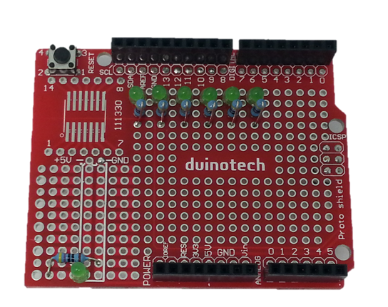
Take six of the 470 Ohm resistors, and bend one leg by 180 degrees:

Take six of the 470 Ohm resistors, and bend one leg by 180 degrees

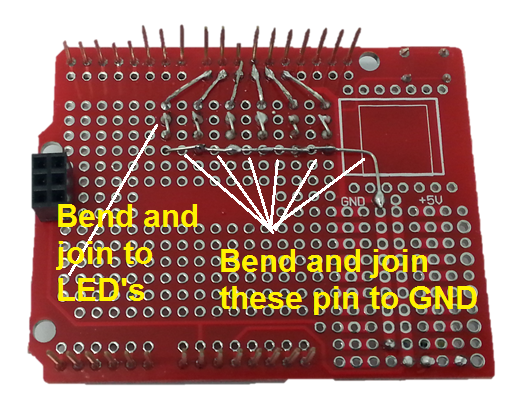
Then insert them in the holes directly below the top LED’s, and solder in place. Take a seventh resistor, and wire it between the power LED and GND as shown. Both legs can be trimmed on the power LED resistor.
Before trimming the other resistors, bend and join the leg closest to the LED, and then bend and join the other legs until they form a continuous wire that connects to GND.
The next components to install are the Tactile Switch, LDR and 1k Ohm resistor. As for the others, solder in place, but do not trim the legs right away.
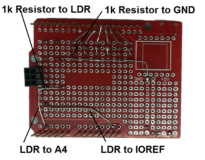
The first thing to do on the other side is to run the bottom-most leg of the LDR to the IOREF pin, and the topmost leg to A4. For the resistor, run one leg to the GND bus made up of the LED legs, and connect the other leg to the LDR leg that goes to A4. This means that we have a voltage divider between IOREF and GND feeding its output into A4.
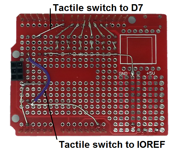
Using an offcut of resistor leg (as we have below) or a piece of wire, link one corner of the tactile switch to pin D7, and the opposite corner to the wire connecting to IOREF.
The potentiometer is next, bend the legs downwards so that they protrude below its body.
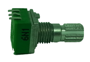
Then mount the potentiometer on the board, making sure that the legs are to the left. We’re going to connect the bottom-most pin to the IOREF wire, so try to line this up if possible. You can also take one of the 10kOhm resistor, and connect it between D7 and GND above the LED’s. This ensures that the input of D7 is held low and doesn’t float.
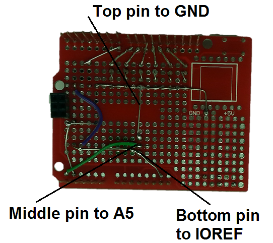
On the reverse of the board, solder the bottom-most pin to IOREF, then run a wire from the middle pin to A5, and from the top pin to GND (we used a resistor leg for this).
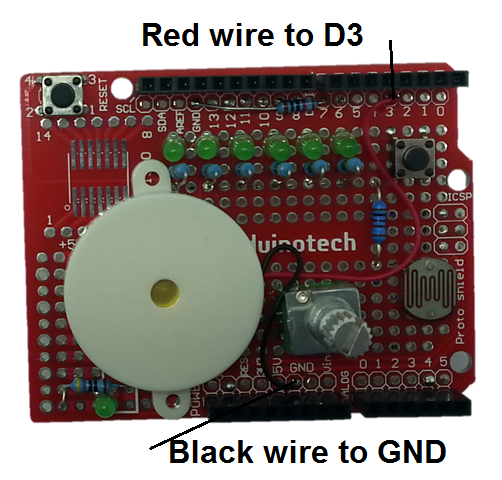
The last solder step is the piezo transducer, which has its red lead connected to D3, and its black lead connected to GND. The leads are quite long, so you might like to trim them before soldering. We used super glue to affix the transducer into the position seen below, but you might want to leave this until you’ve tested the board.
