Firstly, remove all pins on the nano, screen, and current sensor. If you haven't, read the Removing headers article above.
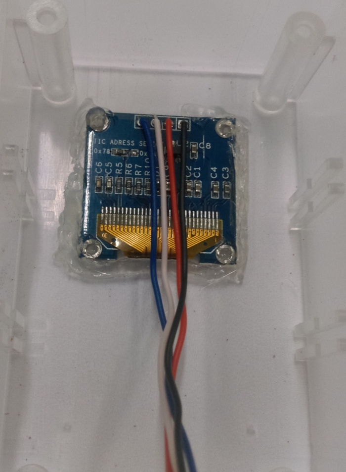
We'll strip some of the WH3032 wire and solder them in place, then cut a hole 19mm x 27mm to mount the screen into the case.
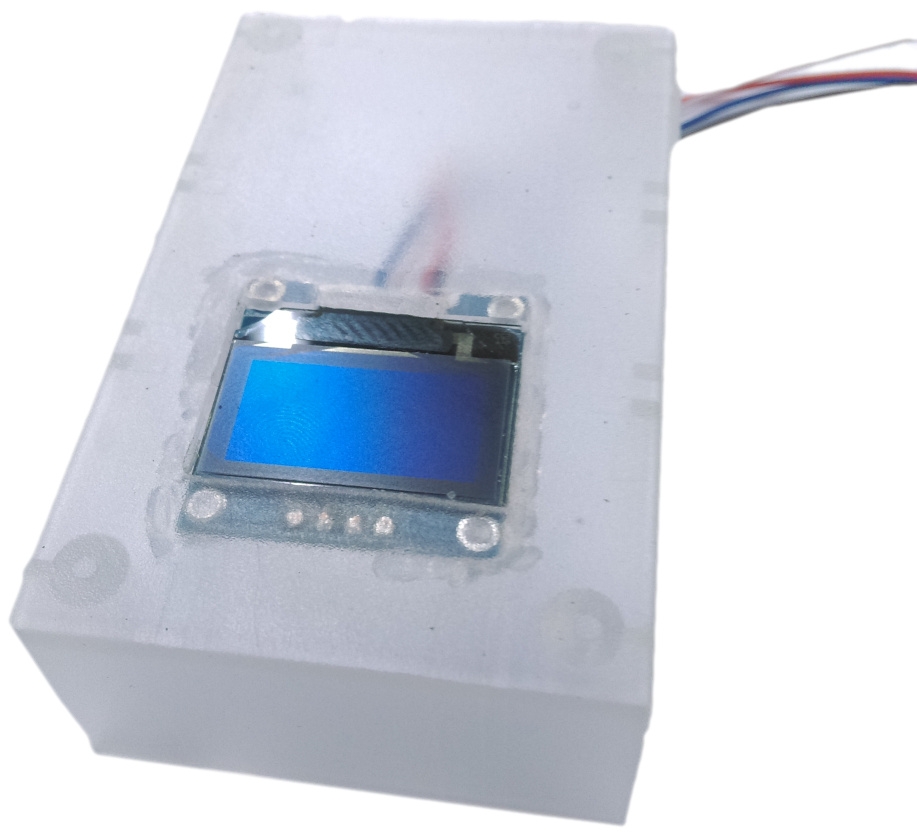
We've used hot glue to hold in place.
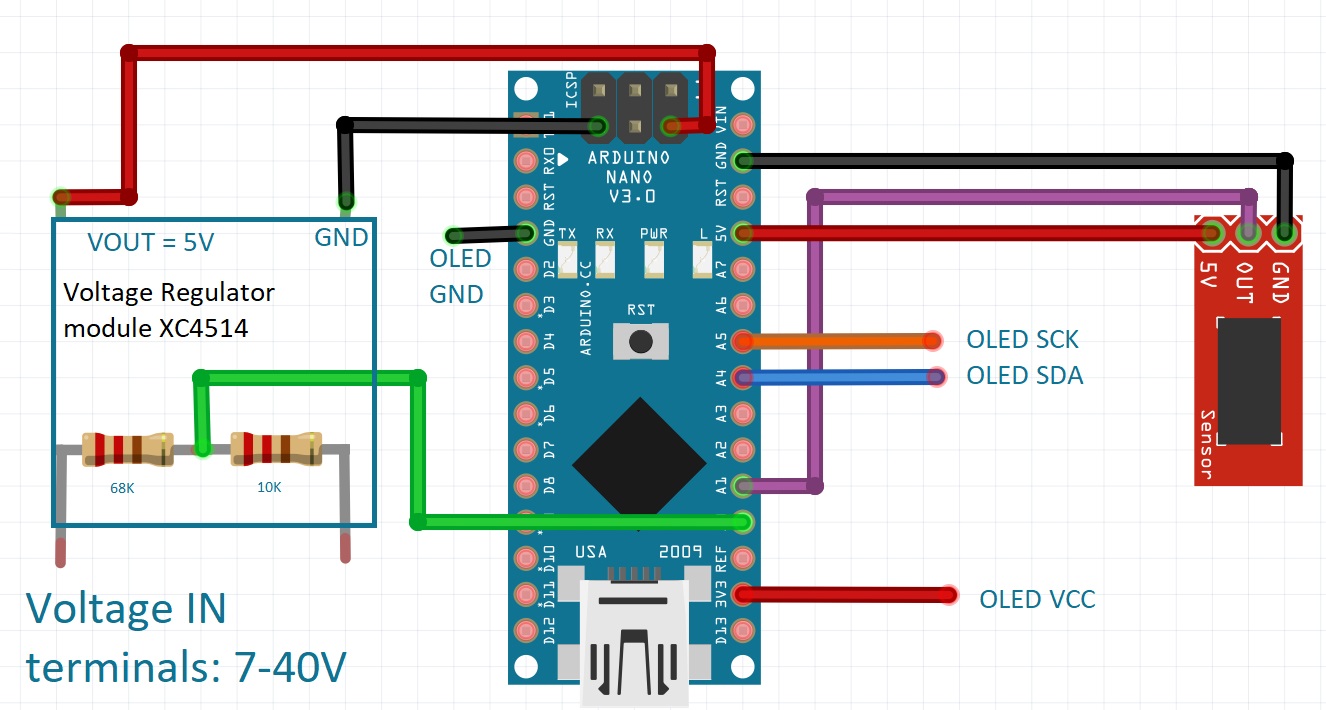
Wrap two of the resistors together and solder together so they form a bond; then bend these to fit in the IN of the voltage regulator module, so that you can later solder a wire to the centre point where they join. Have a look at the pictures below if you're unsure.
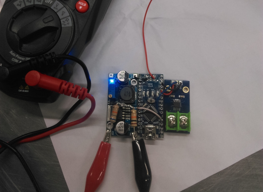
Here we have done the meat of the connections, as there really isn't a lot to the project. Once all the pins have been removed, you can solder up the other connections using the solid core wire, making sure that the amount of wire is small so that they remain firm and tighly held together.
You can notice that the red, 5V wire from the nano isn't connected yet. That is due to the fact that we must first ensure that the regulator is set to 5V through using a multimeter to measure the voltage on the output terminals, and adjusting it until it reaches 5v. Failure to do could quite easily burn out our arduino..
Once the sections are held together and the regulator is set to 5V, solder the OLED screen cables to the Nano and the nano to the regulator. Use some hot glue to mount the nano and sensors to the bottom secton of the jiffy box.
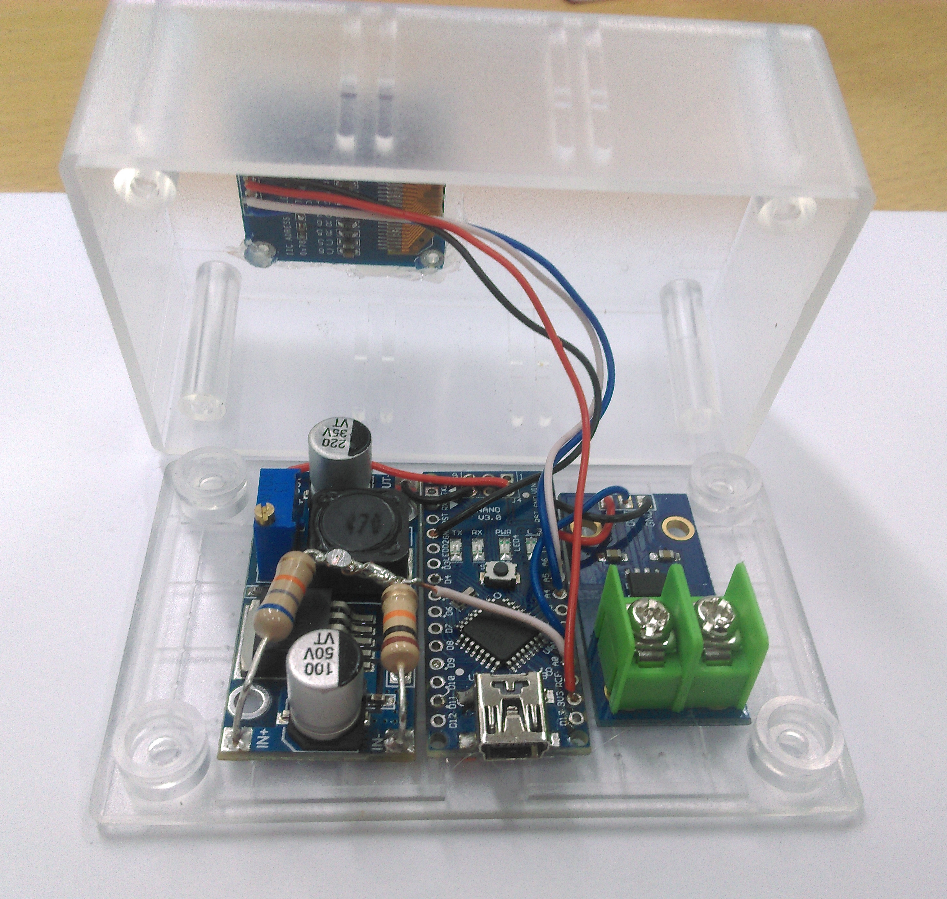
Now all you need to do is put on the input / output terminals, and solder them according to the schematic below.
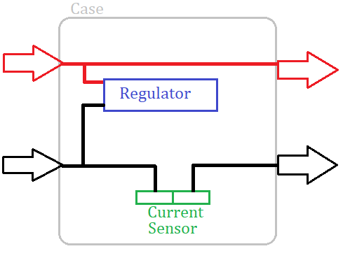
We have connected ours like this, but you can place the terminals any way you like:
.jpg?branch=uat_new)




.jpg?branch=uat_new)