Get creating with this simple and easy, yet fundamental circuit-building tool.
Once upon a time, creating an electric circuit meant getting a slab of wood, some nails or thumb tacks and then running electrical wires to create simple circuits. That slab or timber was often a breadboard, used for slicing bread. Today, the timber breadboard has been replaced with a clever device that makes it easy to connect electronic components without having to run lots of wires – but the name breadboard has stuck.
The great thing about breadboards is that you can create circuits and try things out without soldering. You simply insert your components into the holes on the surface to connect them.
What you need
- Plug to plug jumper leads or any solid core wire small enough to fit – you'll need one piece of wire that's about 6cm long
Breadboard basics
When you look at the breadboard, you'll notice that it is divided into four main sections. The two outside sections are the power rails. This is where you connect the power supply (or supplies) to deliver energy to your creations. The two centre sections are the terminal strips. You'll see that they are labelled with letters and numbers. This is so you can keep track of where each component is connected.
The power rails are also labelled with positive and negative signs. Power runs up the negative side of a power rail, across the terminal strips and back down the positive side of the power rail to complete a circuit. The holes in the breadboard are called tie points.
Creating a basic circuit with a breadboard
Step 1
Strip about 1cm insulation from the end of the wires coming from the battery clip and from the 6cm piece of wire from your breadboard jumper kit.
Step 2
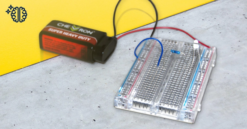
Sit the breadboard on the table in front of you so the positive side of the power rail is on the left and the terminal area is sitting with the column labelled 'a' on the left.
Step 3
Push the anode, or positive lead coming from the LED, into one of the tie points on the leftmost side of the breadboard. The LED's anode is the longer lead coming from the bottom of the LED.
Step 4
Push the cathode, or negative lead, into a tie point in column 'a' of the breadboard. We used the tie point in row 17. So, we could say we put the cathode into position a17.
Step 5
Push one end of the resistor into another tie point in the same row as the LED. We used position b17. Push the other end of the resistor into a tie point in the same row but on the other side of the breadboard, across the dividing channel through the centre. We used position f17 on our breadboard.
We need a resistor to limit the amount of power running from the battery to the LED as the 9V battery we use will provide more power than the LED can handle. Without it, the LED will fail.
Step 6
Take the short piece of wire you prepared in Step 1. Push one end into a tie point adjacent to the right of the resistor, h17 in our case, and the other end into a tie point on the far right of the breadboard, into the column labelled with a '-' sign on the power rail on the right side. The end going into the negative part of the power rail can go into any tie point in that column.
Step 7
Push the end of the red wire coming from the battery clip into a tie point in the '+' column on the left power rail. Push the end of the black wire into the rightmost tie point on the right power rail. It's labelled with a '-' symbol.
Step 8
Insert the battery into the battery clip. The LED should light up.

As you can see, the breadboard makes it very easy to create circuits and to try things out. You can create more complex projects which use more components by simply pushing them into the tie points and seeing what happens as you change the arrangement of the circuit.
If you've created one of these projects or something else altogether, tag us on Facebook or Instagram.

