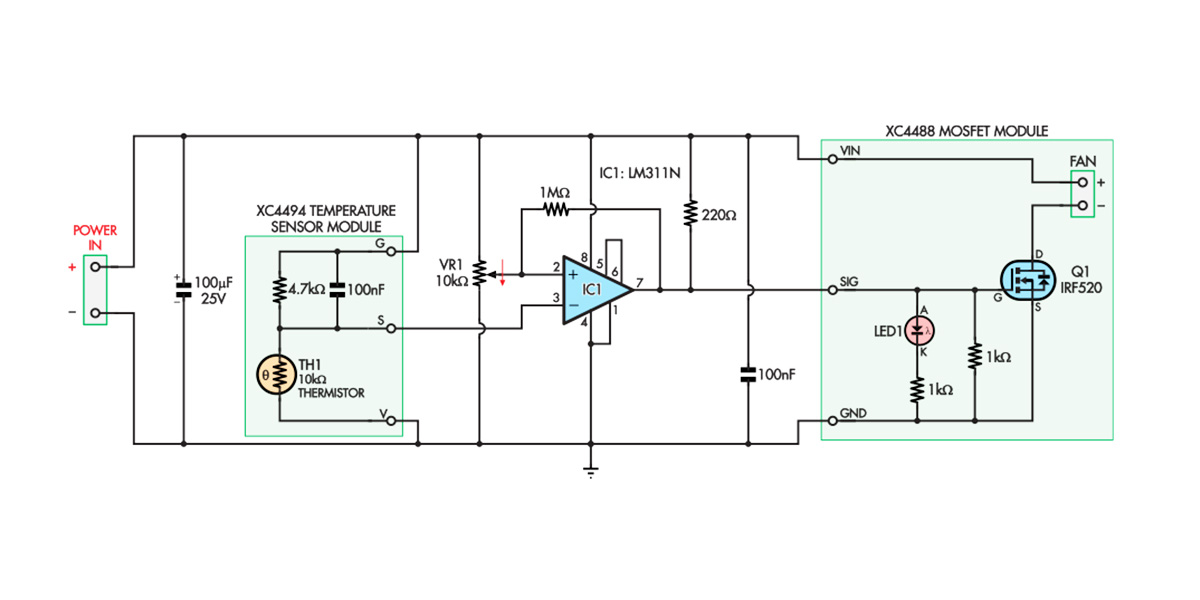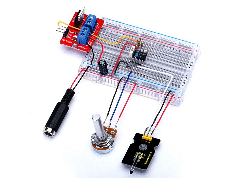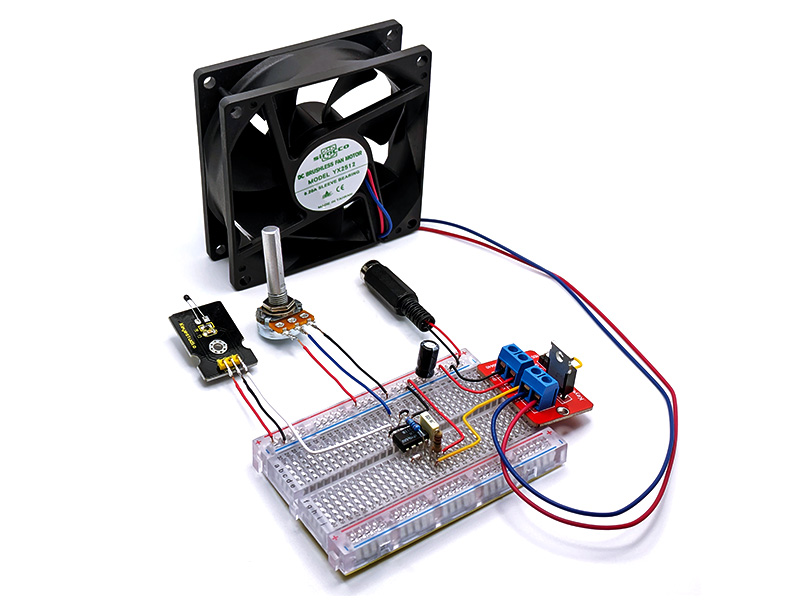
Fig.1 shows the resulting circuit. Note the two boxes that correspond to the two modules. The circuitry and components in those boxes come pre-soldered to the module when you buy it.
One advantage of this analogue approach is that we can run all the circuitry from 12V DC rather than needing to generate a lower voltage to run a microcontroller. That reduces the necessary parts and simplifies the design. The parts we’re using will happily run from 5V up to 18V.
IC1 is a comparator. In simple terms, when the voltage at + pin (pin 2) is higher than the – pin (pin 3), output pin 7 ‘floats’ and is pulled up to 12V by current from the 220Ω resistor. The rest of the time, when the + voltage is lower than the – voltage, IC1 internally connects pin 7 to pin 1, where pin 1 is at 0V (ground).
That means the output is 12V when the + voltage is higher than the other, or at 0V when the + voltage is lower.
By connecting the pin 7 output to the SIG line of the Mosfet Module, the Mosfet switches on when the voltage at pin 7 is 12V, and when the Mosfet is on, it powers the fan.
VR1 is a potentiometer that provides our voltage/temperature setpoint; the wiper voltage can be adjusted between 0V and 12V by rotating the shaft on top. This adjustable voltage is applied to pin 2 of IC1. Thus, IC1 compares the VR1 setting to the voltage from the Temperature Sensor Module, so adjusting VR1’s screw lets you set the temperature at which the output will switch.
Hang on – isn’t it backwards?
While the S pin of the Temperature Sensor Module connects to pin 3 of IC1, its V pin is connected to ground (0V), and the G pin is connected to the 12V supply. That might seem backwards, but the Temperature Sensor module is just a group of passive components, none of which care about polarity, so we’re free to connect it this way.
When wired this way, an increasing temperature causes a decreasing voltage at the S pin. VR1 is also wired ‘backwards’, so that turning the screw clockwise reduces the wiper voltage, to match the behaviour of the Temperature Sensor Module.
The reason for doing it this way is to allow us to provide predictable hysteresis. That is the purpose of the 1MΩ resistor. When IC1’s pin 7 is high, some current flows through the 1MΩ resistor, raising the potentiometer wiper voltage slightly.
Since VR1 is wired backwards, this is the same as reducing the setpoint slightly, meaning that the temperature has to drop a little after the fan switches on before it switches off. That stops it from ‘juddering’ on and off rapidly when the ambient temperature is hovering near the switching setpoint.
If we had wired the circuit up the ‘normal’ way, the hysteresis current would have to be applied to the input connecting to the S terminal of the Temperature Sensor Module. The filter capacitor in that module would have delayed the hysteresis, making it much less effective, as we found in one of our early prototypes!
By reversing the connections to the trimpot and Temperature Sensor module and swapping those inputs, the output of IC1 behaves the same. However, the hysteresis problem is solved, as no capacitor is connected to the trimpot wiper.
The remaining components are 100nF and 100µF supply bypass capacitors that stabilise the circuit by smoothing out any changes to the incoming supply voltage.


